-
1. Purpose of this manual
-
This instruction manual is prepared for technical staff with appropriate training and technical knowledge in the gas pipeline industry in accordance with applicable technical laws and requirements
-
2. Basic Safety Guidelines
-
Operator's Requirements
Operational personnel must be qualified and directed and approved according to their assigned functions. All service and maintenance work should be performed only by persons with proven expertise, including knowledge of occupational safety and environmental protection. Installation, connection, operation, and maintenance should be carried out by professional technicians, especially those familiar with this usage manual. Protection measures should be prescribed in accordance with legal regulations
Specified Use
The MRM II Rotary Gas Meter is designed for the transaction of combustible gas natural gas, city gas, propane gas, butane, refined and dried biogas and other inert, non-corrosive gases, or for volume measurements within the region
The allowable operating pressure ranges from a maximum of 20 bar to a minimum of 25°C to +55°C, depending on the meter design
The manufacturer shall not be liable for any damage caused by improper or unspecified use
on-the-spot safety
wear the necessary personal protective equipment in accordance with national regulations
Operational Safety
The device shall operate only in safe conditions free from technical defects, and the responsibility rests with the operator
Product Safety
The meter is designed, manufactured and tested according to state-of-the-art requirements. It meets all legal requirements and complies with the EC's instructions. This meter is manufactured under perfect conditions at the manufacturing plant and confirmed before shipment
Warranty may be extended only when appropriate installation and operation are required in accordance with this manual
-
3. Type certification
-
• The type certification is obtained in accordance with the KTC regulations to confirm that it is a suitable meter for use in transactions.
• The valid period of calibration may vary depending on the country in which the MRM II rotary meter is installed and is based on national regulations
-
4. Use and Scope
-
The MRM II Rotary Meter is designed for transactional metrology of natural gas and has been approved in accordance with the European requirements of EN12480.
MRM II rotary meters are suitable for installation in the hazardous area of Category 2 (zone 1) II II Gc IICT4
The MRM II rotary meter is suitable for the following gases
• Natural gas, city gas, propane, butane, ethylene, air, nitrogen
• Please contact us separately about gas.
MRM II rotary meters cannot be used for oxygen, acetylene and other corrosive gases and explosive gases or gaseous mixtures
It should also not be used in applications exposed to strong waves. These conditions can increase error and significantly reduce the life of the meter.
-
5. MRM II Rotary Meter Design Overview
-
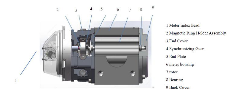
-
Figure 1: MRM II Rotary Meter Sectional View
Note: In case of failure or damage, repairs can only be made by authorized repair companies
-
6. Technical Data
-
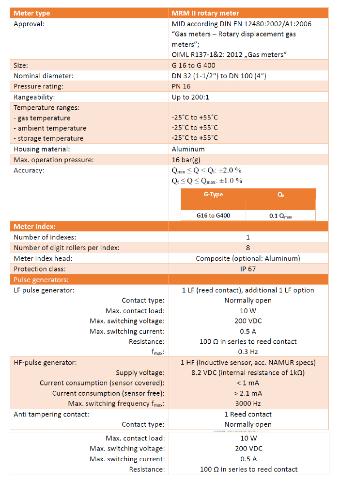
-
Rangeability and pulse weighting data:
-
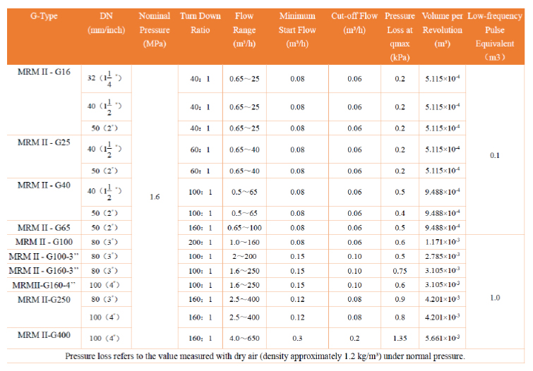
-
7. Installation
-
Installation recommendations and requirements for the MRM II rotary meter:
• Measurements should be installed as horizontally as possible
• No linear inlet or outlet pipe length is required
• A conical strainer is recommended for the entrance of the rotary meter. If the gas flows vertically from bottom to top, an additional conical strainer is also installed at the outlet to protect the meter from dust falling on the piston when the gas flow stops
• Check that the gas flow is the same as the direction indicated on the nameplate of the meter housing
• Avoid strong vibrations and waves at the point of measurement, e.g., solenoid valves when shifting on and off. Vibration of this continuous operation can reduce the long-term strength of ball bearings and pistons and increase wear and damage
• Filter small mesh sizes shall be installed to protect against contaminated suspended particles > 50 μm) during start-up and operation
• The gas should be dry. If condensate can be generated, it is recommended to install condensation traps upstream of the meter (which are integrated in some filter types). In this case, the conditions that can be selected are
o Make sure that it flows from top to bottom.
o Do not install the meter at the lowest point of the pipe
Caution: MRM II rotary meters are not suitable for explosive gases or gaseous mixtures, as well as oxygen and other highly corrosive gases
-
8. Mounting Position Flow Direction
-
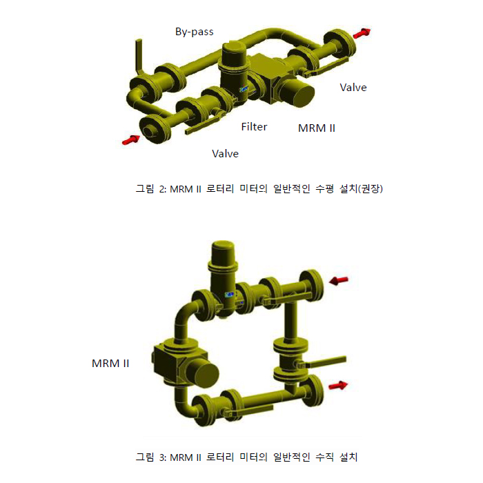
The locations where the rotary meter can be installed are as follows
Horizontal or vertical installation
-
-
The meter is installed horizontally, preferably with the index counter facing up. Check that the gas flow is coming in the same direction as indicated on the nameplate of the meter housing
-
9. Preliminary work and meter installation
-
• Ensure that the following steps are followed before installing the meter
1) Remove the cover sheet from the inlet and outlet of the meter
2) Preparation example of meter: inspect for plug, oil and no damage in transportation
3) If necessary, clean the flange surface with cleaning oil, etc
4) Check that the impeller impeller (piston) rotates easily by blowing air into the meter
5) Before installing the meter, make sure that the pipe is free of contaminants, condensate, dirt or foreign substances. In particular, cleaning the elbow during vertical installation is important to prevent damage to the meter by passing through contaminants, dust and foreign substances
6) Make sure the inner wall of the pipe is clean without accumulated filth or other foreign substances
7) Ensure that there is sufficient installation space between the inlet flange and the outlet flange to install the meter without stress in addition to the length of the meter
8) The meter must be installed in a stress-free place. Therefore, in addition to paragraph (7), proper alignment of the coupling pipe shaft from the inlet to the outlet shaft of the rotary meter shall be strictly observed
• Instruments required for meter installation
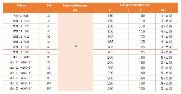
1 Proper and certified gasket
- Dimensions in accordance with DIN EN 15141 or DIN 2690
- Gasket Thickness 2 mm
2 For screws in accordance with DIN ISO 4014, the maximum engagement torque is specified in the following table
3 Strength grade of screw 5.6
-
-
• Installation of the meter itself
1) The meter can be installed in the right or left flow direction
2) Check the meter to make sure that the gas is installed tightly so that it is not strong
3) The meter must be installed stress-free
- Horizontal installation of impeller (piston) shaft, this shall be checked using a horizontal meter
- In the piping design, the installation space of the meter and the thickness of the two seals on both sides shall be considered
- Connecting screws and nuts should be clamped in a crosshairs
Protective coverings are recommended for joining for outdoor installation, especially when the meter is fitted with a volume corrector
• After installing the meter
Welding of pipes and flanges connected to installed meters is not permitted
-
10. lubrication
-
1) Use the oil recommended by Metreg Technologies.
2) Specified oil: Viscosity grade 15, Kinematic viscosity 40°C: 16.2 mm2/s, 110°C: 4.44 mm2/s, Viscosity index 205, Flash point 178°C
3) Before commissioning the meter, install the meter properly and inject oil as described in Chapter 12 and paragraphs 7 and 8
4) To fill the meter with oil, the meter must be depressurized
5) follow the procedures described
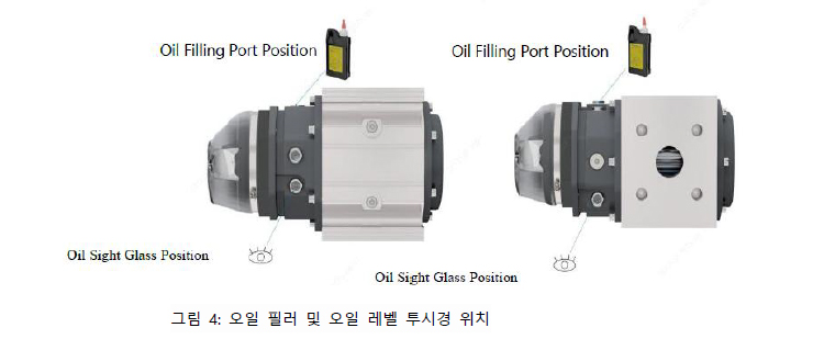
a. Unplug it
-
-
b. Inject designated oil through filling holes at the back and front. No oil is required for index counters
c. Fill the oil to the center mark line of the oil goggle glass and close the inlet hole with a plug
-

-
d. Do not overfill oil, instructions for maximum oil injection depending on installation location and meter size are shown in the table below
-

-
e. Re-seal the filling hole with screws
-
11. Maintenance
-
1) Rotary meters generally do not require any special service. The maintenance interval depends on the driving conditions.
Metreco recommends checking oil levels regularly at least once a year
2) Oil should be replaced every five years
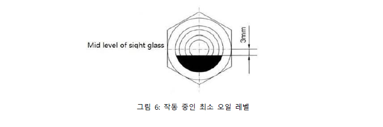
3) If the oil level is 3 mm lower than the center line of the oil see-through window glass, the oil shall be added to the center line
-
-
4) Oil needs to be replaced when the oil color changes or the oil level is higher than the center mark. It means that the oil is deformed or contains impurities.
5) MRM II Rotary Meter Repair should only be done by competent and certified professionals, such as service engineers at Metreco.
6) Do not break the seal. If only one of the seals is damaged or damaged in the storage of natural gas in accordance with MID (2004/22 / EG), the meter shall not be used in the previous measurements.
-
12. A trial run
-
The operation procedure of the MRM II rotary meter shall be followed by the installation and leakage test of the connection
1) Work should be done under the scrutiny of the appointees who coordinate and control the activities
2) Slowly open the upstream valve Figure 2 and Figure to pressurize the pipe until the operating pressure is reached
3) Pressure increase rate shall not exceed 350 mbar/s
4) Completely open the upstream valve at the operating pressure level
5) Slightly open the downstream valve (Figure 2 and Figure 3).
6) The downstream valve can be fully opened at the operating pressure level
7) Test leakage at operating pressure
8) Measurement of pressure loss is carried out at two measurement points of the meter with benchmark values for one or more flow rates.
For maintenance work, if the piston rotates smoothly or there is a change in performance, it is a good indicator that the initial pressure loss and the actual pressure loss should be less than 50% of the initial value at start-up.
The following relationship is valid
-

-
13. Decomposition
-
The operation procedure of the MRM II rotary meter shall be followed by the installation and leakage test of the connection
1) Work should be done under the scrutiny of the appointees who coordinate and control the activities
2) Proper ventilation treatment in the installation room
3) Depressurize only the area where the ignition source is not activated to atmospheric pressure
4) Slowly reduce the operating pressure, e.g. 350 mbar/
5) When the pipe is fully decompressed, open the bolts and nuts of the flange
6) Carefully remove the meter from the pipe connection
7) Drain the oil from the meter through the drain plug
-
14. Pulse generator
-
The operation procedure of the MRM II rotary meter shall be followed by the installation and leakage test of the connection
Two low frequency pulse (LF) generators are connected to the meter index counter head for normal pulse transfer.
The functions of these two LF pulses are as follows
• 2 LF pulsars for flow measurement
• One LF pulsar for anti-tampering anti-tampering option allows a second LF pulsar for flow measurement to be plugged into the meter index counter head
-

-
Caution
All pulse generators are safe by nature. If the meter is installed in the hazardous area, it should be connected to an external device, such as an electronic calibrator, basically only through a device, such as a safety circuit, etc
-
15. Pressure Measurement Point
-
The operation procedure of the MRM II rotary meter is subject to the installation and leakage test of the connection
There are two pressure test points, as shown in Figure 9. The normal pressure test points are marked with "this, on the other side". The two pressure test points are designed for connecting steel pipes with a diameter of 6 mm.
Steel tubes shall conform to DIN EN 103051 and shall not be made of nonmetallic materials such as stainless steel or plastic. Pipe connections or fittings shall conform to DIN 2353
-

-
16. Temperature measurement point
-
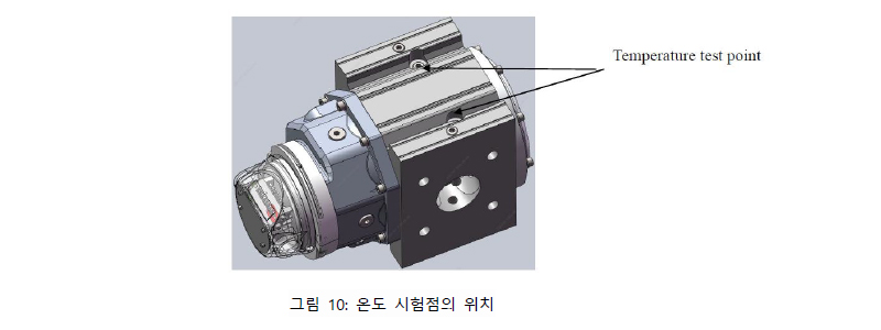
There are two temperature test points, as shown in Figure 10, where the normal temperature test points are marked as "", and the difference is "".
The temperature tab is locked with screws (G 14"). If using the temperature tab, remove the plug screw and replace it with a G 14" integrated threaded temperature pocket (thermo well). The temperature pocket is designed for a temperature sensor with a diameter of 6 mm
If the temperature tab of the rotary meter is not used, the temperature measurement point shall be located 3DN upstream of the meter
-
-
17. Cleaning up
-
Do not use solvents when cleaning meters from dust and filth. For cleaning purposes, it is also suitable to use a wet cloth only
-
18. Transportation and storage
-
Rotary meters and accessories should be stored in their original packaging. Fix the measuring instrument so that it does not rotate or slip.
Care must be taken when carrying to loading and measuring points
Some requirements for transportation and storage of the meter are as follows
• The meter covers both flanges with a protective cover
• For transport, the meter is not filled with oil
• keep out rain and moisture
• It prevents mechanical vibration or shock.
• Unpack and verify
o Check the packaging list with a description of all items received
o Inspect each item for damage
-
19. Annex B
-
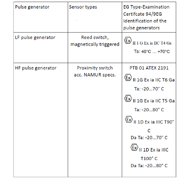
The pulse generator is ATEX certified and shown as below
-
|

